
December 21, 2023
N64 Explorations
Part 1: First steps
This is the introduction to a series I will be making on the Nintendo 64 console. In this article, I’ll start by telling you about my personal connection with the console (feel free to skip this section if you want to get into the technical stuff right away). Then, we’ll work our way up to making a basic disassembler and decoding our first instructions!
Table of Contents
A Blast from the Past
Some of my most vivid and oldest memories are of my siblings and I playing Super Smash Brothers at my grandparent’s house during the holidays. My parents had bought an N64 a couple of years earlier for my older siblings. I was the youngest, but also the most avid player by far. I remember getting up extra early and waking up my mom to ask if I could play before getting ready for school. Almost every single day!
Whenever there was a grown-up nearby, I’d pester them to no end so they would read the game dialog for me. My grandfather was always happy to help, but unbeknownst to me, he would make up the most ridiculous dialogues instead of actually reading them! And speaking of getting help, I would only play Banjo-Kazooie if my mom was around because I was mortally afraid of Clanker! These fond memories date back to around 2001-2002.
Time passed, and other consoles came along. I did own a GameCube and a Wii, but I always came back to the N64. I started tinkering with emulators, changing texture packs and messing with random hex codes. I had no clue what I was doing, but very slowly I was getting interested in the tech behind the games I was playing. At the same time, I started publishing “funny” Super Mario 64 clips on YouTube (which was brand new at that time). These were incredibly cringe-worthy, but I had fun making them and editing them with Movie Maker. All the cool kids were playing Brawl or Melee, but my friends and I were still playing good ol’ Smash64.
Fast-forward to when I started college. I didn’t know many people who were interested in playing, and my original N64 console was barely holding on for dear life anyway. Sadly it and the cartridges had suffered damage in a house fire. To scratch that itch, I started watching videos about my favorite games and discovered there was a vibrant community around the N64 and speedrunning. Listening to explanations of how certain glitches and shortcuts work transported me way back to when I was a kid just messing around with emulators.
I’ve always had this interest and fascination for the N64, from my earliest memories to the present day. Now that I’ve transitioned from Physics to Computer Science, I finally have the tools and knowledge to be able to dive deeper into the console. It’s time for me to truly start exploring the Nintendo 64!
Expectations
I’m nowhere near an expert in hardware engineering or the N64. In fact, I would consider myself a beginner in both of these. What I do have is a genuine passion and curiosity for the subject.
So, this series will be written from the point of view of someone learning everything from scratch. A great deal of effort has been made by community members to consolidate knowledge about the N64, but my impression is that there still is not a lot of beginner-friendly material. Most of the learning material online is highly condensed summaries of hundreds if not thousands of hours of research, and is usually targeted at people who are already knowledgeable about the N64. I want to try something different. Instead of writing condensed summaries, I want to document the full journey, with the hiccups and all. I’ll share my thought process and interesting tidbits as I stumble upon them. Hopefully, this makes it more approachable and less overwhelming for beginners.
My main goals with this series are to
- Learn more about the hardware and software of the N64 by making an emulator.
- Aggregate resources and document my learning journey as much as possible.
- Generate discussions and interest around the N64.
To that first point: I am aware that making an emulator is a long and arduous process, but bear in mind that the emulator project is just a vehicle for learning, not an end in and of itself.
Getting started
I will be using Rust to write the emulator. This is a language I’m familiar with and which affords me both high and low-level capabilities. Keep in mind that this isn’t a Rust tutorial, I won’t dwell long on the language itself. I will try to document the code and explain my reasoning to make it broadly understandable, and I encourage you to follow the series even if you don’t know Rust.
I’ll start by creating a new project.
mkdir tattlecd tattle
Why “tattle”?
It’s an iconic move in Paper Mario that gives the player information about their surroundings and enemies. And since that’s kind of what I’m doing here, learning and talking and stuff, I thought it was fitting. It sort of makes sense, just don’t think too hard about it.
Alright uhhh… What now? Where to start? Emulating a modern-ish console is daunting because the hardware itself is quite complex and there’s no obvious place to start. Everything seems hopelessly tangled in a web of interdependency. I spent a long time just trying to figure this out to no avail, going down from one rabbit hole to another.
Instead, I’ll opt for a top-down approach. I’ll do as if I actually had a functioning emulator and work my way down as I encounter features that need to be implemented. Obviously, nothing will work at first, but at least it gives us a direction.
So, let’s start by choosing a game and trying to run it. “Real” games are way too complex for my (non-existent) emulator. Instead, I will opt for what’s called a test ROM.

ROM is a term referring to read-only memory. Game cartridges like the N64’s have read-only memory banks dedicated to holding the game’s data that are baked in at the factory when the cartridge is made. In the context of retro-gaming and emulation, ROM has become synonymous with “game data”. When I say “test ROM”, I mean a digital file holding tests that our emulator can run. There are many such test suites available, and we might get to try a bunch of them later on, but for now, I’ll focus on Dillon’s test suite. The reason is that these tests are fairly basic and don’t require a sophisticated emulator to run.
Let’s add them to the repo.
mkdir romswget "https://github.com/Dillonb/n64-tests/releases/download/latest/dillon-n64-tests.zip" -O temp.zipunzip temp.zip -d roms/dillon-n64-testsrm temp.zip
.z64 files? These are all the test ROMs. As for the extension, the “64” part is easy: the files contain instructions and data for an N64 ROM. The “z” specifies that the data is encoded in a big-endian format hence “z64” means a big-endian N64 ROM. In contrast, “.n64” is a little-endian N64 ROM.
Endianness has to do with the order in which bytes of a word are ordered. The gist is that different systems have different endianness. Since the N64 is big-endian, cartridge dumps (the process of transferring the ROM from the cartridge into a digital format) are also big-endian. But, most computers that run emulators are little-endian, thus some dumps come already pre-processed into little-endian. In any case, Rust exposes some useful utilities to work with different endianness, so this shouldn’t be much of a problem.
For now, we’ll focus on one particular test ROM: basic.z64. What do we need to do to actually run this test? Well, before we can run anything, the emulator has to be able to recognize and understand whatever is in the ROM. It’s time for the first task: making a simple disassembler.
The disassembler
The purpose of a disassembler is to recognize instructions from raw binary and pretty-print them to the user. Specifically, it transforms sequences of bytes back into assembly instructions. A disassembler is a good place to start because it’s fairly self-contained. You don’t need to emulate the whole console to fully complete this part. Furthermore, it allows us to start recognizing some instructions, which is one step further towards a working emulator.
To understand how to carry out this process, we need some reference documents on the N64’s instruction set. After a bit of googling, I stumbled upon the Emulation Development Discord server, which has a room dedicated to the N64. The users over there were incredibly nice and helpful, and eventually, they recommended two amazing resources that I will use throughout this series:
Shoutouts to BigBass and the other contributors for their work on the Wiki.

Yeah, it is. But it’s fairly well written and I’ll use very little of it for now. We just need to learn a bit about how instructions are laid out, so bear with me.
A quick skim reveals this gem
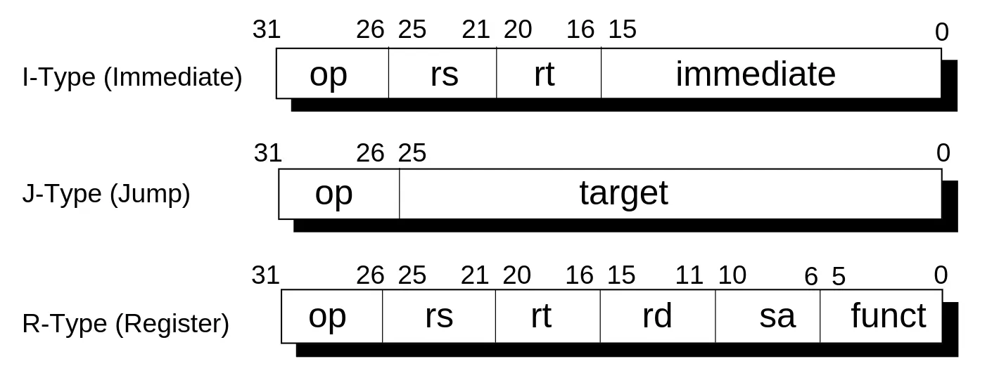
Figure 1 - Instructions come in three flavors: immediate, jump and register. Each has a different layout. (VR4300 manual, section 1.4.3, p.39)
This shows how different instruction types are laid out in memory. Each subdivision corresponds to an operand. It also describes each instruction as being composed of 4 bytes (32 bits). I peeked at the full instruction list (Chapter 16), and some instructions deviate completely from these three categories. Nonetheless, this is a good place to start.
I’ll create a workspace and put the core and disassembler in separate crates. The core will contain all the high-level functionality of our emulator, and the disassembler will just consume it:
# Turn crate into workspacecat > Cargo.toml<<EOF[workspace]resolver = "2"members = ["crates/*"]EOF# Create cratesmkdir cratescargo new crates/core --lib --name tattle_corecargo new crates/disassembler --name tattle_disassemblerThe reason for separating the core and the disassembler is simply that the disassembler is a separate tool used to examine ROM content, not a part of the emulator per se. That said, in the process of making the disassembler, we’ll also end up implementing important features in the emulator core.
As dependencies for the disassembler, I’ll add
clapto build a CLI.anyhowfor basic error handling.const-chunksto consume iterators in fixed-size chunks (this may no longer be needed if you come from the future).
cargo add --package tattle_disassembler --features derive clapcargo add --package tattle_disassembler anyhowcargo add --package tattle_disassembler const-chunksFinally, I’ll make the disassembler depend on the core
cargo add --package tattle_disassembler --path crates/core/Before we go on to make the disassembler, we need a basic representation of what an instruction is. Let’s add that to the core.
mod instruction;We start with just a basic skeleton:
#[derive(Debug)]pub enum Instruction {    Unknown}
impl Instruction {    /// Decode a 32-bit instruction from big-endian bytes.    pub fn from_be_bytes(data: [u8; 4]) -> Self {        // `be` refers to "big-endian"        Self::from(u32::from_be_bytes(data))    }
    /// Instruction is unrecognized.    pub fn is_unknown(&self) -> bool {        matches!(self, Self::Unknown)    }}
impl From<u32> for Instruction {    fn from(data: u32) -> Self {        Instruction::Unknown    }}
Easy! All instructions are unknown, for now.
The From<u32> implementation defines the actual decoding logic. Currently, we don’t recognize any instructions, so they are all mapped to Instruction::Unknown.
Making a CLI
With that initial setup done, we can start building the interface for our disassembler. First, we declare the module
mod cli;Then, we can use clap’s derive API to build our CLI:
use std::{path::PathBuf, str::FromStr};
use anyhow::{anyhow, bail};use clap::Parser;
/// N64 ROM disassembler. The disassembly is piped to standard output.#[derive(Parser)]pub struct Cli {    /// The path to the file to read.    pub path: PathBuf,
    /// Print raw data as binary. Cannot be used with the `raw_hex` flag.    #[arg(long, conflicts_with = "raw_bin")]    pub raw_hex: bool,
    /// Print raw data as hex. Cannot be used with the `raw_bin` flag.    #[arg(long, conflicts_with = "raw_hex")]    pub raw_bin: bool,
    /// The range to disassemble. If the range is not specified, the entire file is disassembled.    ///    /// Ranges can be specified as `start..end`, `start..`, `..end`, or as a single value.    /// Hexadecimal values (prefixed with `0x`) are interpreted as byte offsets, while decimal    /// values are interpreted as word offsets.    #[arg(value_parser = parse_range)]    pub range: Option<DisassemblerRange>,}
/// Specifies an offset range into an N64 Rom.#[derive(Debug, Clone, Copy)]pub struct DisassemblerRange {    /// The range's start (inclusive).    pub start: Option<usize>,    /// The range's end (exclusive).    pub end: Option<usize>,    /// Special predicate for single-value ranges.    pub is_single: bool,}
That Parser derive macro from clap is doing all the heavy lifting. It’ll implement all the machinery to get us a nice CLI with great help messages.
Notice here how we use a custom value_parser for ranges. I built a custom parser that recognizes both byte and word ranges, with potentially open bounds. With this parser, these are all valid inputs: 3..10, 3..0x100, 0x10..0x100, ..10, 10.., 10, .., etc. To be clear, you don’t need something this flexible, I just thought it was fun, so I did it.

…Maybe, just a little. Anyway, here’s the parsing code:
impl FromStr for DisassemblerRange {    type Err = anyhow::Error;
    fn from_str(s: &str) -> Result<Self, Self::Err> {        // Split range start and end        let Some((start_str, end_str)) = s.split_once("..") else {            // No ".." pattern: parse as a single value            let value = parse_hex_or_decimal_to_address(s)?;            return Ok(DisassemblerRange {                start: Some(value),                end: None,                is_single: true,            });        };
        let start = (!start_str.is_empty())            .then(|| parse_hex_or_decimal_to_address(start_str))            .transpose()?;        let end = (!end_str.is_empty())            .then(|| parse_hex_or_decimal_to_address(end_str))            .transpose()?;
        Ok(Self {            start,            end,            is_single: false,        })    }}
/// Parse a rangefn parse_range(s: &str) -> anyhow::Result<DisassemblerRange> {    let range = DisassemblerRange::from_str(s)?;
    // Check if the range is word-aligned    if range.start.map_or(false, |start| start % 4 != 0)        || range.end.map_or(false, |end| end % 4 != 0)    {        bail!("Start and end of range must be word-aligned (4 bytes).");    }
    Ok(range)}
/// Parse a hexadecimal or decimal value. If the value is hexadecimal it is interpreted as an address./// If the value is decimal it is interpreted as a word offset and then converted to an address.fn parse_hex_or_decimal_to_address(input: &str) -> anyhow::Result<usize> {    input        .strip_prefix("0x")        // Try to parse as hexadecimal address        .map(|hex| usize::from_str_radix(hex, 16))        // Try to parse as decimal word offset (and convert to address)        .unwrap_or_else(|| input.parse::<usize>().map(|word_offset| word_offset * 4))        .map_err(|_| anyhow!("Expected decimal or hexadecimal value, got \"{input}\""))}
With that in place, we can start cooking up the CLI using the Instruction type we created in the core:
mod cli;
use anyhow::{bail, Context};use clap::Parser;use const_chunks::IteratorConstChunks;
use tattle_core::instruction::Instruction;
use cli::Cli;
fn main() -> anyhow::Result<()> {    // Get args from CLI parser    let Cli {        path,        range,        raw_hex,        raw_bin,    } = Cli::parse();
    // Read target file    let data = std::fs::read(path).context("Failed to read file")?;
    // Check file size    if data.len() % 4 != 0 {        bail!("File size is not a multiple of 4 bytes (word-aligned).");    }
    // Get range bounds and fill omitted values.    let (start, end, is_single) = match range {        Some(range) => (            range.start.unwrap_or(0),            range.end.unwrap_or(data.len()),            range.is_single,        ),        None => (0, data.len(), false),    };
    // Compute how many bytes to skip and take    let skip = start;    let take = if is_single {        4    } else {        end.saturating_sub(start)    };
    // Decode instructions    let word_iter = data        .iter()        .copied()        .skip(skip)        .take(take)        .const_chunks::<4>()        .map(|word| (word, Instruction::from_be_bytes(word)))        .enumerate();
    // Display disassembly line    for (word_offset, (word, instruction)) in word_iter {        println!(            "{}",            DisplayDisassembled {                byte_offset: word_offset * 4 + skip,                word,                instruction,                raw_hex,                raw_bin            }        );    }
    Ok(())}
/// Utility struct that formats a disassembled instructionstruct DisplayDisassembled {    byte_offset: usize,    word: [u8; 4],    instruction: Instruction,    raw_hex: bool,    raw_bin: bool,}
impl std::fmt::Display for DisplayDisassembled {    fn fmt(&self, f: &mut std::fmt::Formatter<'_>) -> std::fmt::Result {        // Write offset indicator        write!(f, "[0x{:08X}]", self.byte_offset)?;
        // Write raw data (hex or bin).        // Also write binary raw data if the instruction is unknown.        if self.raw_hex {            write!(f, " ({:08X})", u32::from_be_bytes(self.word))?;        } else if self.raw_bin || self.instruction.is_unknown() {            write!(                f,                " ({:08b} {:08b} {:08b} {:08b})",                self.word[0], self.word[1], self.word[2], self.word[3]            )?;        };
        // Write instruction        write!(f, " {:?}", self.instruction)?;
        Ok(())    }}
Phew! There’s some CLI handling and a Display implementation, but the highlighted part is the most important. It iterates over the data isolating the bytes within the specified range, then it takes them in groups of four to form words. Instructions are decoded out of that (while also keeping the raw data around for debugging purposes).
Just to make things a bit easier in the future, let’s add a command alias to run the disassembler
[alias]disassemble = "run --package tattle_disassembler --"Let’s give it a try. The first 0x1000 bytes of a ROM are typically reserved for the header and the IPL3 (we’ll get back to these at some point). So, Let’s try printing the first “real” instruction located at 0x1000:
cargo disassemble roms/dillon-n64-tests/basic.z64 0x1000[0x00001000] (00111100 00000100 10111111 11000000) UnknownRight?
The first part in brackets is the byte offset into the ROM. The second part in parentheses is the raw binary data of the instruction, and the last part is the decoded instruction, which is currently Unknown. To discover which instruction that is, we’ll have to learn how to decode instructions.
Decoding instructions
The manual has a ton of information about instructions, notably Chapter 3 (CPU Instruction Set Summary) and Chapter 16 (CPU Instruction Set Details). While I highly recommend giving these chapters a skim just to get a sense of the different instruction categories and their operands, they are not that useful for learning about decoding in practice. Fortunately, the manual has a dedicated summary of instruction encoding that we can use.
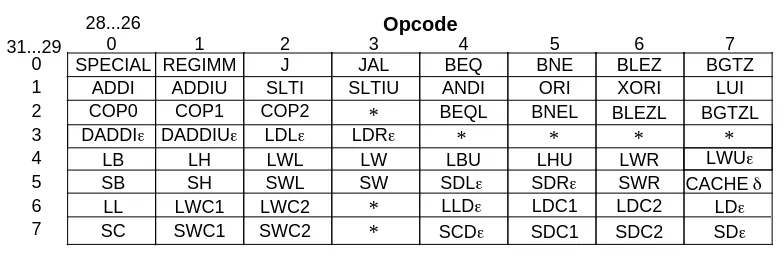
Figure 2 - Opcode bit encoding (VR4300 manual, section 16.7, p.544). Instructions are identified
by looking at bits 31..29 and 28..26, which corresponds to the opcode bit segment
This diagram shows how to use the instruction’s opcode, which is located in bits 26 to 31, to identify an instruction. The upper bits of the opcode (31..29) and the lower bits (28..26) act as indexes into the instruction matrix. For example, upper bits 001 (decimal 1) and lower bits 101 (decimal 5) identify the ORI instruction, with the full opcode being 001101.
It took me a while to figure out, but while most opcode values uniquely identify an instruction, some specify an instruction class instead. Instructions within an instruction class are further identified by values in other fields. We’ll discuss these classes as they become relevant. I found this information in Chapter 8 (Instruction Encoding) of the MIPS IV instruction set manual.
MIPS IV? Are you not aware that the N64’s VR4300 processor uses the MIPS III architecture?
I am aware, but I couldn’t for the life of me find the MIPS III manual, and the MIPS IV manual still contains a ton of information relevant to the MIPS III. In fact, MIPS IV is compatible with all prior versions.
Let’s go back to the instruction we tried to disassemble earlier.
[0x00001000] (00111100 00000100 10111111 11000000) UnknownThe opcode is 001111. By comparing with the bit encoding diagram, we can deduce this corresponds to LUI. To fully decode this instruction, we need a function that can identify it and extract its operands. Let’s take a look at what the manual has to say on this particular instruction:
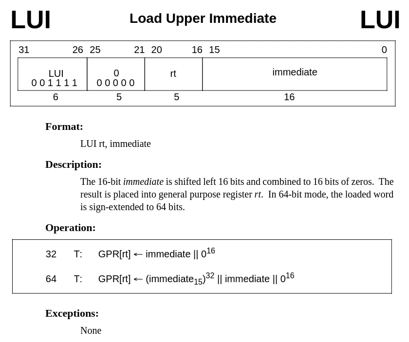
Figure 3 - Entry for the LUI instruction (VR4300 manual, section 16.6, p.457). The instruction
has two operands: a target register rt, and a 16-bit immediate value.
To decode this instruction, the opcode needs to be recognized, and the bits 16 to 20 and 0 to 15 must be isolated to yield the rt and immediate operands respectively.
/// Decoded instruction.#[derive(Debug)]pub enum Instruction {    /// Load Upper Immediate.    Lui { rt: u32, immediate: u32 },    /// Unknown instruction.    Unknown,}
impl From<u32> for Instruction {    fn from(value: u32) -> Self {       Instruction::Unknown        match (data >> 26) {            0b001111 => Instruction::Lui {                rt: (data << 11) >> 27,                immediate: data & 0x0000_FFFF,            },            _ => Instruction::Unknown,        }    }}
Notice how we use bit fiddling with shifts and masks to isolate the op, rt and immediate bit segments.
Decoding LUI is fairly easy, we only have to match the opcode. Notice how the decoding logic is infallible. If an unknown instruction is encountered, it will be marked as InstructionKind::Unknown. In the future, we may want to change that to account for other types of failures.
While we’re at it, we can add a more flexible Debug derive to pretty-print instructions. This will become increasingly useful as the enum gets bigger and more repetitive in the future.
cargo add --package tattle_core debugifyUsing this crate, we can format all fields named “immediate” as 16-bit hex values. Since the immediate operand will be repeated in many instructions, this saves a lot of repetitive and error-prone boilerplate.
#[derive(Debug)] #[derive(Debugify)] #[debugify(field_name(immediate = "0x{:04X}"))]enum instruction {I made debugify to help with applying formatting rules based on field names (among other features).
With this in place, our disassembler is ready to decode something:
cargo disassemble roms/dillon-n64-tests/basic.z64 0x1000[0x00001000] Lui { rt: 4, immediate: 0xBFC0 }Wonderful! Our first instruction.
We will make some modifications to simplify the process of adding new instructions in the future and prevent bugs, so please bear with me as we take a little detour to talk about macros.
An aside: Procedural macros, boilerplate and correctness
Looking at the declaration of Instruction and its From<u32> implementation, the keen-eyed among you may have realized that there’s a direct mapping between the name of the fields and how they should be decoded. We can use that to cut a lot of boilerplate and ensure that the fields are always decoded correctly using the power of procedural macros.
Procedural macros must live in a separate compilation unit, so let’s create a crate for all our macro needs.
cargo new --lib crates/macros --name tattle_macrosWe’ll also need to mark it as a procedural macro crate:
[package]name = "tattle_macros"version = "0.1.0"edition = "2021"
 [lib] proc-macro = true
Finally, let’s add the usual dependencies to work with macros
cargo add --package tattle_macros proc-macro2 # Better token streamscargo add --package tattle_macros quote # Quasi-quotingcargo add --package tattle_macros --features full syn # Input parsingcargo add --package tattle_macros heck # Case conversionThe idea is to generate functions for each bit segment and for each instruction. This is what the following Decode derive macro accomplishes. It looks like a bunch of code, but it’s really not as bad as it looks and I’ll walk you through it.
use heck::ToSnakeCase;use proc_macro::TokenStream;use quote::{format_ident, quote};
/// Implements associated methods to decode each instruction variant.#[proc_macro_derive(Decode)]pub fn decode(input: TokenStream) -> TokenStream {    // Parse input to enum ast    let ast = syn::parse_macro_input!(input as syn::ItemEnum);    let enum_ident = &ast.ident;
    let instruction_decoder_fragments = ast.variants.iter().filter_map(|variant| {        // Ignore tuple and unit variants        let syn::Fields::Named(fields_named) = &variant.fields else {            return None;        };
        let variant_ident = &variant.ident;
        // Instruction decoder function name        let fn_ident = syn::Ident::new(            &variant_ident.to_string().to_snake_case(),            variant_ident.span(),        );
        // Field assignments        let fields = fields_named.named.iter().map(|field| {            let field_ident = field.ident.as_ref().unwrap();            let decoder = field_ident_to_segment_decoder_path(field_ident);            quote! {                #field_ident: #decoder(data),            }        });
        // Instruction decoder fragment        Some(quote! {            fn #fn_ident(data: u32) -> Self {                Self::#variant_ident { #(#fields)* }            }        })    });
    // Generate instruction and bit segment decoders    let segment_decoders = segment_decoders_fragment();    quote! {        impl #enum_ident {            #(#instruction_decoder_fragments)*
            #segment_decoders        }    }    .into()}
fn field_ident_to_segment_decoder_path(ident: &syn::Ident) -> proc_macro2::TokenStream {    let decoder_name = match ident.to_string().as_str() {        "rs" | "base" => "rs",        "rt" => "rt",        "rd" => "rd",        "sa" => "sa",        "target" => "target",        "immediate" | "offset" => "immediate",        _ => {            return syn::Error::new_spanned(ident, format!("unknown operand `{ident}`"))                .to_compile_error()        }    };    let decoder_ident = format_ident!("{decoder_name}");    quote! { Self::#decoder_ident }}
fn segment_decoders_fragment() -> proc_macro2::TokenStream {    quote! {        /// Bits 26-31        fn op(data: u32) -> u32 {            data >> 26        }
        /// Bits 21-25        fn rs(data: u32) -> u32 {            (data << 6) >> 27        }
        /// Bits 16-20        fn rt(data: u32) -> u32 {            (data << 11) >> 27        }
        /// Bits 11-15        fn rd(data: u32) -> u32 {            (data << 16) >> 27        }
        /// Bits 6-10        fn sa(data: u32) -> u32 {            (data << 21) >> 27        }
        /// Bits 0-5        fn funct(data: u32) -> u32 {            (data << 26) >> 26        }
        /// Bits 0-25        fn target(data: u32) -> u32 {            (data << 6) >> 6        }
        /// Bits 0-15        fn immediate(data: u32) -> u32 {            data & 0x0000_FFFF        }    }}
The segment_decoders_fragment is just a big constant fragment for all the bit segment decoders that isolate specific operands in a word. If you’re not sure what these functions represent, please refer back to Figure 1.
The field_ident_to_segment_decoder_path enforces specific field names for the instruction (i.e. one of the aforementioned bit segments). Some names are mapped to a canonical name (e.g. base to rs) since they are essentially alternate names for the same bit segment. This prevents errors and ensures consistent naming.
Most of the actual logic is contained in the decode function directly, especially in the highlighted parts. The first highlight generates each field assignment, the second generates a decoder function for each instruction, and the third one brings everything into the full impl block.
Now, to be clear, you don’t need a macro like this. There’s nothing a macro can do that you couldn’t have written out yourself. One could even argue that all I’ve done is replace perfectly plain code with a bunch of macro code! That said, I like the macro approach because it ensures each instruction variant is consistently named and correctly decoded, and it cuts down on some pure boilerplate that contains no real logic. We only have one real instruction variant currently, so the boilerplate aspect is not super relevant now, but by the end of this article it will make a big difference, I promise!
We could’ve gone one step further to also generate the From<u32> impl as part of the same macro, but macro code has diminishing returns. If we generate the From impl, then we need a helper attribute to specify the opcode, so in the end there will essentially be the same number of lines (replacing one match arm for an attribute in the enum). It also greatly complexifies the macro, especially when taking into account the instruction classes that we discussed earlier since those are identified differently. Finally, it’s no longer obvious what the macro does and it feels like the kind of “magic” code that’s annoying to maintain. What we have right now feels like a nice middle ground where we generate the repetitive error-prone stuff without obscuring too much of the core logic.
Let’s add our new macro crate to the core crate
cargo add --package tattle_core --path crates/macrosHere’s what the code looks like with this Decode macro:
use debugify::Debugify;
 use tattle_macros::Decode;
/// Decoded instruction. #[derive(Debugify)] #[derive(Debugify, Decode)]#[debugify(field_name(    [immediate, offset] = "0x{:04X}",    target = "0x{:08X}",))]pub enum Instruction {    /// Load Upper Immediate.    Lui { rt: u32, immediate: u32 },    /// Unknown instruction.    Unknown,}
impl From<u32> for Instruction {    fn from(data: u32) -> Self {        match (data >> 26) {        match Self::op(data) {            0b001111 => Instruction::Lui {                rt: (data << 11) >> 27,                immediate: data & 0x0000_FFFF,            },            0b001111 => Self::lui(data),            _ => Instruction::Unknown,        }    }}
Notice how we use the op and lui functions that were generated by our macro. Much nicer.
Adding the remaining instructions
Let’s try the next instruction. Remember, instructions are 4 bytes, so we bump the address by 4:
cargo disassemble roms/dillon-n64-tests/basic.z64 0x1004[0x00001004] (00110100 00001000 00000000 00001000) UnknownBack into terra incognita. Once again we identify the opcode: 001101, and once again, we can refer to the bit encoding diagram to find out this is ORI. The manual entry for ORI (VR4300 manual, section 16.6, p.485) tells us that the operands are rs (bits 21..25), rt (bits 16..20) and a 16-bit immediate (bit 0..15). We have everything in place to handle this:
/// Decoded instruction.#[derive(Debugify)]#[debugify(field_name(immediate = "0x{:04X}"))]pub enum Instruction {    /// Load Upper Immediate    Lui { rt: u32, immediate: u32 },    /// OR Immediate    Ori {        rs: u32,        rt: u32,        #[debugify("0x{:016b}")]        immediate: u32,    },    /// Unknown instruction    Unknown,}
impl From<u32> for Instruction {    fn from(value: u32) -> Self {        match op(value) {            0b001111 => Self::lui(data),            0b001101 => Self::ori(data),            _ => Instruction::Unknown,        }    }}
Easy. Notice how we specified the immediate’s formatting to binary since this is a bitwise operation. It’s easier to reason about when the immediate is presented in binary.
Next instruction (the one at 0x1008). The opcode is 101011, which corresponds to the SW instruction. According to the manual (VR4300 manual, section 16.6, p.515), it has operands base (in place of the rs bit segment), rt, and offset (in place of the immediate bit segment).
#[derive(Debugify)]#[debugify(field_name(immediate = "0x{:04X}"))]#[debugify(field_name([immediate, offset] = "0x{:04X}"))]pub enum Instruction {    // ...    /// Store Word    Sw { base: u32, rt: u32, offset: u32 },    // ...}
impl From<u32> for Instruction {    fn from(value: u32) -> Self {        match op(value) {            // ...            0b101011 => Self::sw(data),            // ...        }    }}
The “offset” fields correspond to byte offsets, so we also format them as hex.
Now that we have a couple of instructions down, we’ll start to see repetitions
cargo disassemble roms/dillon-n64-tests/basic.z64 0x1000..0x1018[0x00001000] Lui { rt: 4, immediate: 0xBFC0 }[0x00001004] Ori { rs: 0, rt: 8, immediate: 0x0000000000001000 }[0x00001008] Sw { base: 4, rt: 8, offset: 0x07FC }[0x0000100C] Lui { rt: 30, immediate: 0x0000 }[0x00001010] Ori { rs: 30, rt: 30, immediate: 0x0000000000000000 }[0x00001014] (00001100 00000000 00000100 10111010) UnknownLet’s take a closer look at that last instruction, which is unknown. Same as before, we look up the opcode, find the operands and add it to our decoder:
#[derive(Debugify)]#[debugify(field_name([immediate, offset] = "0x{:04X}"))]#[debugify(field_name([immediate, offset, target] = "0x{:04X}"))]pub enum Instruction {    // ...    /// Jump and Link    Jal { target: u32 },    // ...}
impl From<u32> for Instruction {    fn from(value: u32) -> Self {        match op(value) {            // ...            0b000011 => Instruction::jal(data),            // ...        }    }}
The target operand represents an address so we format it as hex.
The next instruction is a fun one. Running the disassembler gives this:
[0x00001018] (00000000 00000000 00000000 00000000) UnknownSame as usual, right? Well, not quite. See, the 000000 opcode doesn’t uniquely identify an instruction. Instead, according to the bit encoding diagram, it corresponds to the SPECIAL instruction class. There are many instructions inside this instruction class.
Fortunately, the manual also provides a bit encoding diagram specifically for SPECIAL instructions:
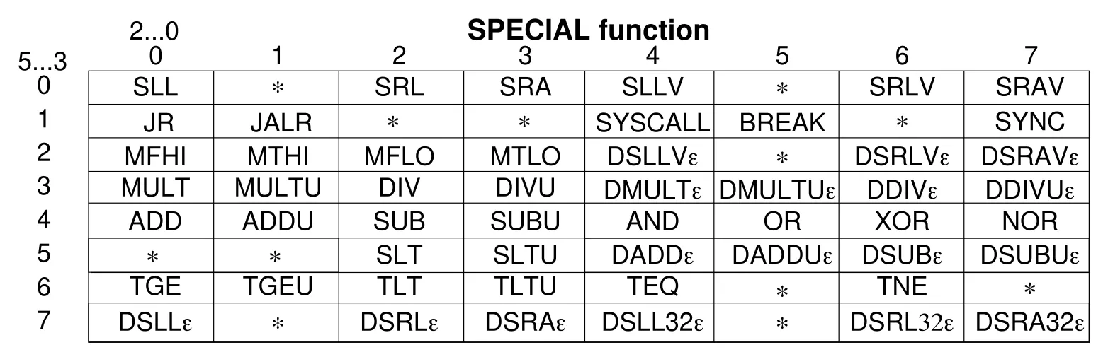
Figure 4 - Bit encoding for instructions in the SPECIAL instruction class (VR4300, section 16.7,
p.544). Special instructions are identified using bits 5..3 and 2..0, which corresponds to the
funct bit segment.
A nil opcode specifies the SPECIAL instruction class, and the nil funct operand further identifies the SLL instruction. To illustrate what this instruction looks like, here’s the entry for SLL in the manual (VR4300 manual, section 16.6, p.503).
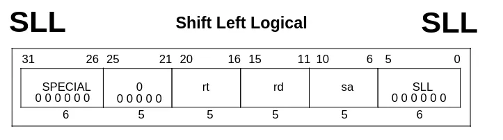
Notice the opcode and funct bit segments, both nil.
This isn’t too hard to implement, we just need to make sure to properly handle SPECIAL instructions in the From<u32> implementation:
pub enum Instruction {    // ...    /// Shift Left Logical    Sll { rd: u32, rt: u32, sa: u32 },    // ...}
impl From<u32> for Instruction {    fn from(value: u32) -> Self {        match op(value) {            // Special instructions            0b000000 => match Self::funct(data) {                0b000000 => Self::sll(data),                _ => Instruction::Unknown,            },            // ...        }    }}
Now, let’s take a look at the disassembled instruction:
[0x00001018] Sll { rd: 0, rt: 0, sa: 0 }The manual entry states that the effect of this instruction is as follows:
The contents of general-purpose register
rtare shifted left bysabits […]. The result is stored in general-purpose registerrd.
So, what does this instuction do? Shift the contents of register 0 by 0 bits and store the result in back register 0? What? That doesn’t do anything, why would anyone want to do that?
Exploring the reason for this oddity reveals some interesting insights on how the VR4300 works regarding instruction delays, but I’ll save that for the next part of this series. See this as a bit of foreshadowing!
I’ll skip over the next instructions since it’s just a matter of repeating the same procedures we saw earlier, over and over. However, this brings an interesting question: when to stop? Our goal here is to decode all the instructions from the basic test ROM, nothing more for now. Well, we need to remember that a ROM contains both instructions and other data, where that other data is not meant to be executed. The trouble is that plain data can look just like instructions. They’re both just bytes after all. And besides, physical ROM chips come in predefined sizes so ROMs are usually padded with meaningless filler to bulk the ROMs up to one of those predefined sizes. So, how can we tell instructions from the rest?
A well-formed program will only execute actual instructions, so by running a ROM or by analyzing the program flow, we can differentiate the instruction segments from the rest. That’s sort of a chicken-and-egg problem though because we can’t currently execute the ROM yet (remember the disassembler doesn’t actually execute any instructions). To get the full picture, we can look at the original assembly that was used to generate the test ROM. Bear in mind that we don’t have the original assembly for most games out there, but, since these test ROMs were made specifically for this purpose, they give us access to a ton of useful information. In this case it’s possible to simply reason about the execution and decide which sections of the ROM are actually instructions.
Note that the original assembly will not map exactly one-to-one with our disassembly since they use macros and pseudo-instructions. One example is LI (a pseudo-instruction that is not actually in the VR4300 instruction set) being converted to LUI and ORI.
Another important thing to bear in mind is that some definitions are scattered across multiple files and there’s no indication of where a particular macro comes from. You just have to dig I guess ¯\_(ツ)_/¯. For example, in the original assembly linked above, the first instruction is a macro named N64_INIT(), which is defined in a totally different file. We can see that N64_INIT does contain the LUI, ORI and SW sequence that we decoded earlier, which is a good sign!
All in all, to fully disassemble the test ROM, we end up roughly with the following instructions:
/// Decoded instruction.#[derive(Debugify, Decode)]#[debugify(field_name(    [immediate, offset] = "0x{:04X}",    target = "0x{:08X}",))]pub enum Instruction {    /// Add    Add { rs: u32, rt: u32, rd: u32 },    /// Add Immediate    Addi { rs: u32, rt: u32, immediate: u32 },    /// Add Immediate Unsigned    Addiu { rs: u32, rt: u32, immediate: u32 },    /// Add Unsigned    Addu { rs: u32, rt: u32, rd: u32 },    /// And Immediate    Andi {        rs: u32,        rt: u32,        #[debugify("0b{:016b}")]        immediate: u32,    },    /// Branch On Equal    Beq { rs: u32, rt: u32, offset: u32 },    /// Branch On Equal Likely    Beql { rs: u32, rt: u32, offset: u32 },    /// Branch On Greater Than Zero    Bgtz { rs: u32, offset: u32 },    /// Branch On Not Equal    Bne { rs: u32, rt: u32, offset: u32 },    /// Branch On Not Equal Likely    Bnel { rs: u32, rt: u32, offset: u32 },    /// Doubleword Add Immediate    Daddi { rs: u32, rt: u32, immediate: u32 },    /// Jump    J { target: u32 },    /// Jump and Link    Jal { target: u32 },    /// Jump and Link Register    Jalr { rs: u32, rd: u32 },    /// Jump Register    Jr { rs: u32 },    /// Load Byte    Lb { base: u32, rt: u32, offset: u32 },    /// Load Byte Unsigned    Lbu { base: u32, rt: u32, offset: u32 },    /// Load Upper Immediate    Lui { rt: u32, immediate: u32 },    /// Load Word    Lw { base: u32, rt: u32, offset: u32 },    /// Load Word Unsigned    Lwu { base: u32, rt: u32, offset: u32 },    /// OR Immediate    Ori {        rs: u32,        rt: u32,        #[debugify("0b{:016b}")]        immediate: u32,    },    /// Shift Left Logical    Sll { rd: u32, rt: u32, sa: u32 },    /// Shift Right Logical    Srl { rt: u32, rd: u32, sa: u32 },    /// Store Word    Sw { base: u32, rt: u32, offset: u32 },    /// Unknown instruction    Unknown,}
impl From<u32> for Instruction {    fn from(data: u32) -> Self {        match Self::op(data) {            // Special instructions            0b000000 => match Self::funct(data) {                0b000000 => Self::sll(data),                0b000010 => Self::srl(data),                0b001000 => Self::jr(data),                0b001001 => Self::jalr(data),                0b100000 => Self::add(data),                0b100001 => Self::addu(data),                _ => Self::Unknown,            },            0b000010 => Self::j(data),            0b000011 => Self::jal(data),            0b000100 => Self::beq(data),            0b000101 => Self::bne(data),            0b000111 => Self::bgtz(data),            0b001000 => Self::addi(data),            0b001001 => Self::addiu(data),            0b001100 => Self::andi(data),            0b001101 => Self::ori(data),            0b001111 => Self::lui(data),            0b010100 => Self::beql(data),            0b010101 => Self::bnel(data),            0b011000 => Self::daddi(data),            0b100000 => Self::lb(data),            0b100011 => Self::lw(data),            0b100100 => Self::lbu(data),            0b100111 => Self::lwu(data),            0b101011 => Self::sw(data),            _ => Self::Unknown,        }    }}
Our disassembler is now fully able to disassemble the basic test ROM.
Conclusion
In this first part, we’ve seen how to implement instruction decoding and we’ve applied this to make a simple disassembler. More specifically, we
- Discussed the content of ROMs (specifically test ROMs).
- Learned how to decode instructions using the bit encoding as a reference.
- Implemented a simple procedural macro to make it easier to add instructions.
- Made a CLI for our disassembler to tie it all together.
In the next part, we’ll implement these instructions to actually execute the test ROM.